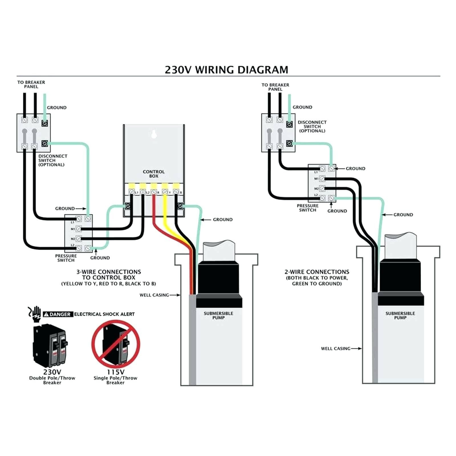
3 Wire Well Pump Data Wiring Diagram Schematic 3 Wire Submersible Well Pump Wiring Diagram
A. WIRING DIAGRAMS A. WIRING DIAGRAMS 20 21 Typical Wiring A Diagrams 3 1 2 5 36 97 1 L1 T1 T2 T3 L2 L2 3 To Pump Motor Ground Level Control Ground Pressure Switch Lower Upper Electrode Input Power (As Required By Level Control) To Fused Disconnect Or Circuit Breaker 3Ø Furnas Magnetic Starter Line Load Line Load 3 Phase Starter Magnetic.

⭐ 110 Volt 3 Wire Submersible Pump Wiring Diagram ⭐ Boderless creations
A single phase submersible pump starter circuit diagram is used to control the flow of electricity through an electrical system, and it is essential for any project involving the installation of a water pump. There are different types of starters available on the market, each with its own set of features.

LIDER [2 HP][Single Phase Submersible Pump Starter][LBMSP 2036] indiacitymart
In this video you will learn about the single phase submersible pump starter wiring. This is the complete guide about wiring 1 phase submersible pump or the.
208V 1 Phase Motor Submersible Pump Starter Wiring Diagram Pdf Database
A submersible pump also called an electric submersible pump. it is a pump that can be fully submerged in water. the motor is hermetically sealed and closed coupled to the body of the.
Single Phase Submersible Pump Starter Wiring Diagram Pdf Wiring Diagram
Single Phase Submersible Starter Wiring | Submersible starter Connection |Float Switch Wiring Diagram with Manual On/Off Switchhttps://youtu.be/gPbk-amZvfITw.

Single Phase Submersible Pump Starter Wiring Diagram Free Wiring Diagram
01. Single Phase Submersible Pump: A Submersible Pump Is an Air-Tight Sealed Motor Close-Coupled to The pump's body. The Main Advantage of This Type of Pump is That it Prevents Pump Cavitation, a Problem Associated With a High Elevation Difference Between the Pump and the Fluid Surface.
Submersible Motor Starter wiring Single Phase Submersible Starter Wiring YouTube
Today I am here to share with you the 3 phase submersible pump wiring diagram. In which I control a three-phase submersible pump motor using a magnetic contactor. Not only a contactor but also install the thermal overload relay which will protect the motor from burning in case of overcurrent flow to the circuit.

3 phase submersible pump starter wiring diagram
A standard submersible pump wiring diagram provides step-by-step directions for connecting the necessary wires and switches. The diagram starts with the power source, which is typically a breaker box or fuse panel.

44 Luxury Single Phase Submersible Pump Starter Wiring Diagram Jet pump, Well pump
A submersible pump comprises of a number of parts, including an electrical circuit and wiring, a control panel, start switch, and a motor, which are all connected together in order to run the system safely and efficiently. These components need to be properly connected by an experienced electrician to ensure safe and reliable operation.

Electric Motor Diagram Explanation Motor Motors Electric Types Electrical Overview Does Elect
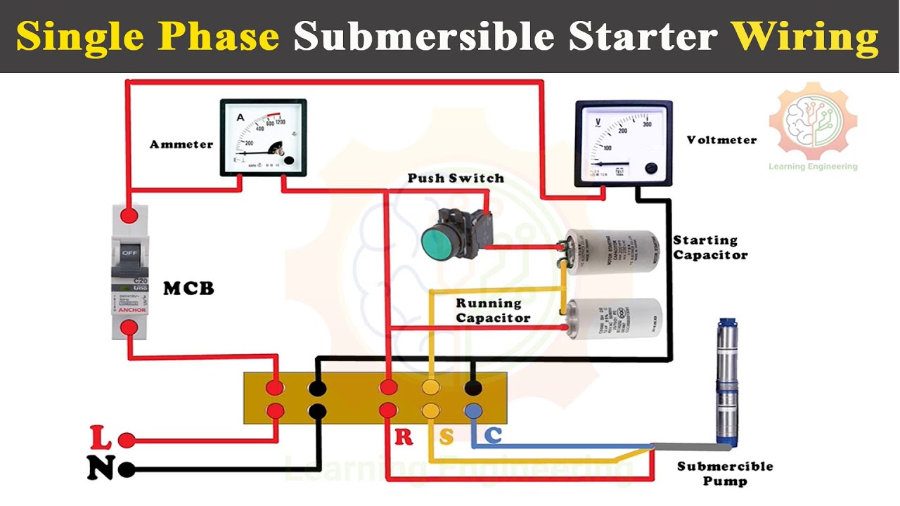
Step-1: Gather All Necessary Equipment and Material Through the whole process, the single-phase 3-wire submersible pump wiring diagram will help you a lot to stick in the right path. Along with the wiring diagram, we need to use some essential elements, and they are: A capacitor A resistible thermal overload and

Single Phase Submersible Pump Motor Wiring Diagram Wiring Diagram
Step-1: Determination of the Number of Wires The 220-volt submersible pump you are using can consist of either two-wire or three-wire. You will have to determine the wire number first, start the pump., and follow the conduit back for it.

How To Wire Single Phase Motor Starter
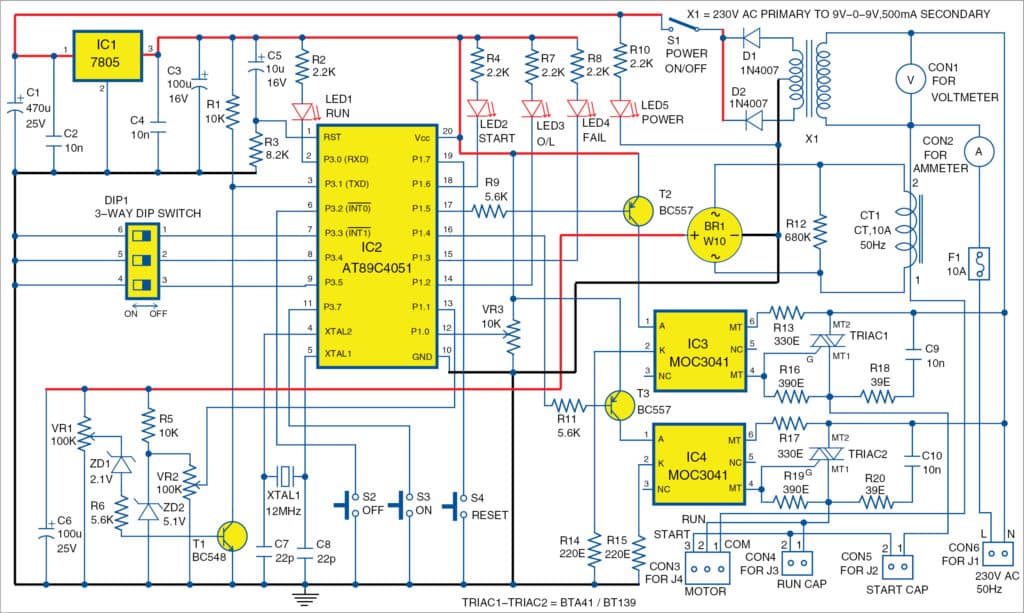
Electrical Tutorials 4.03K subscribers Subscribe 659 239K views 6 years ago A complete guide about Single Phase Submersible Motor Starter Wiring Diagram explanation or single phase 3 wire.
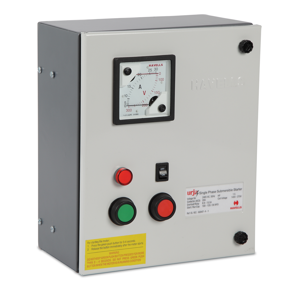
Single Phase Submersible Pump Starter Circuit Diagram Wiring Diagram
The video shows how to configure your Submersible pump motor with auto cut-off function. (Semi automatic function). Normally in all single phase submersible pump we have to press start switch for two second to switch on the pump. and wait till the tank is filled and then we have to press stop button to stop the pump this is so problematic.

[View 18+] Rangkaian Panel Wiring Diagram Panel Pompa Submersible 1 Phase
First, see the 3 phase submersible pump wiring diagram and after that,we will explain each step of the below connection diagram. In the above figure, we have shown the L1, L2, L3 and N-line input power in red, yellow, blue, and black. Among them, the red, yellow, and blue three-phase wires, and the black wire is the neutral wire.
Bestly Myson Wiring Centre Diagram
Here is the complete diagram of single phase submersible pump starter wiring diagram below. Single Phase Submersible Pump Motor Control box wiring Explanation video tutorial

Single Phase Submersible Pump Panel Wiring Diagram Wiring Diagram
Single-phase submersible pump control box wiring diagram - 3-wire submersible pump wiring diagram. In the submersible pump control box, we use a capacitor, a resit-able thermal overload, and a DPST switch (double pole single throw). The wiring connection of the submersible pump control box is very simple. Here is the complete guide step by step.